 EN
EN

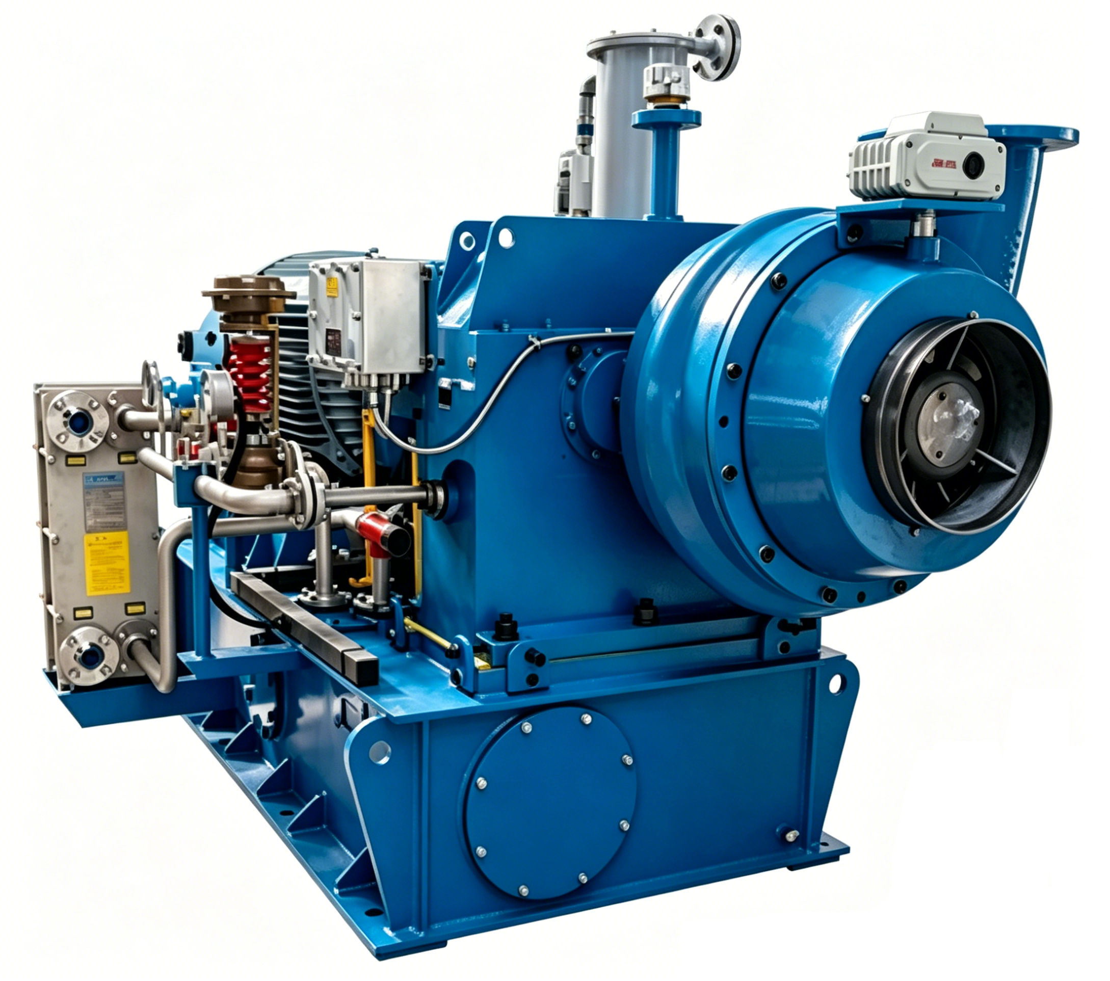
အဓိက စက်မှုဒီဇိုင်း – အင်ပေါ်လာ၊ ဟော့စ်နှင့် ဘီယာရင်းများ
အခြေခံအားဖြင့် ကြာရှည်ခံမှုအတွက် အင်ပေါ်လာ၏ တည်ဆောက်မှုနှင့် ဘလေးဒ်များ၏ ဖွဲ့စည်းပုံ
အင်ပေလာသည် စက်မှုလေပေးစက်များ၏ လည်ပတ်နေသော နှလုံးသားဖြစ်ပါသည်— ယန္တရားမှ စွမ်းအားကို လေစီးကောင်းမှုနှင့် ဖိအားအဖြစ် တိုက်ရိုက်ပောင်းလဲပေးပါသည်။ နှစ်များစွာကြာမျှ အဆက်မပါသော အသုံးပြုမှုအတွက် စိတ်ခေါ်မှုများကို ခံနိုင်ရည်ရှိရန်အတွက် အင်ပေလာသည် အထူးသောင်းခံနိုင်သော ပစ္စည်းများဖြစ်သည့် အလူမီနီယမ် အိုးထည်၊ ဒတ်က်တိုင်း သံမဏိ သို့မဟုတ် စတိုင်န်လက်စ်သံမဏိ တို့ဖြင့် ဖန်တီးထားရပါမည်။ ပိတ်ထားသော အင်ပေလာများ (အနက်မှုန်းနှစ်ခုကြားတွင် အနက်မှုန်းများ ပိတ်ထားခြင်း) သည် အတွင်းပိုင်း ပြန်လည်စီးဆင်းမှုကို အနည်းဆုံးဖြစ်အောင်ပြုလုပ်ခြင်းဖြင့် သန့်စင်သောလေအသုံးပြုမှုများတွင် အကောင်းဆုံး စွမ်းဆောင်ရည်ကို ရရှိစေပါသည်။ အနက်မှုန်းများကို တစ်ဖက်သာ ပိတ်ထားသော အင်ပေလာများသည် အနည်းငယ်သော အမှုန်များကို လက်ခံနိုင်ပါသည်။ အနက်မှုန်းများ၏ ပုံစံ— ရှေ့သို့ ကွေးသောပုံစံ၊ နောက်သို့ ကွေးသောပုံစံ သို့မဟုတ် အလယ်မှ အပြင်သို့ ထွက်သောပုံစံ— သည် ဖိအား–စီးကောင်းမှု မှုန်းခေါ်မှုကို သတ်မှတ်ပေးပါသည်။ နောက်သို့ ကွေးသော အနက်မှုန်းများသည် မှုန်းခေါ်မှု များပါးသော အားသုံးမှုကို ပေးစေပါသည်။ ထို့ကြောင့် အစိတ်အပိုင်းများ အားလုံး အပိတ်မှုဖြစ်ပါက မော်တာအပေါ် ဖိအားများ လျော့နည်းစေပါသည်။ အရေးကြီးသော ဒီဇိုင်းအသေးစိတ်များတွင် အနက်မှုန်းများ၏ အထူကို အကောင်းဆုံးဖြစ်အောင် ပြုလုပ်ခြင်း၊ အနက်မှုန်းများ၏ အများဆုံး အားသုံးမှုကို ကာကွယ်ရန် အများကြီးသော အမျှဝေမှုများ ပြုလုပ်ခြင်း၊ အပူခွဲခြင်းကြောင့် ဖောင်းပွမှုများ ဖြစ်ပါကလည်း အမှန်တကယ် လည်ပတ်မှုကို ထိန်းသိမ်းနိုင်ရန် အတိကျသော စက်ဖြင့် ဖွင့်ထားသော အပေါက်များနှင့် အသေးစိတ်မှုန်းများ ပါဝင်ပါသည်။ နေရာတိက်တိက်နှင့် အကောင်းဆုံး အကွာအဝေးဖြင့် ဖန်တီးထားသော အနက်မှုန်းများသည် လေစီးကောင်းမှုကို အနည်းငယ်သော လှုပ်ရှားမှုများနှင့် အသုံးပြုမှုကို လျော့နည်းစေပါသည်။ ထိုသို့သော လှုပ်ရှားမှုများသည် ဘီယာရီနှင့် အိမ်အတွင်းပိုင်းများ ပျက်စီးမှုကို ဖြစ်စေသည့် အဓိကအကြောင်းရင်းများ ဖြစ်ပါသည်။ အင်ပေလာ၏ အနက်မှုန်းများကို လေ၏ အပူချိန်၊ အမှုန်များ၏ ပမာဏနှင့် အသုံးပြုမှု အကြိမ်ရေအားလုံးနှင့် ကိုက်ညီအောင် ပြုလုပ်ခြင်းဖြင့် အကောင်းဆုံး စွမ်းဆောင်ရည်ကို အချိန်ကြာမှုအထိ ထိန်းသိမ်းနိုင်ပါသည်။
အိမ်ရာအမျိုးအစား (ဗောလျူတ်၊ အင်လိုင်း၊ ပလပ်) နှင့် အဆက်မပြတ်ဖောက်သည့်အားအောက်တွင် ဖွဲ့စည်းပုံဆိုင်ရာ ခိုင်မာမှု
အိမ်ရာသည် အရှိန်မြင့်စက်အိမ်ရာကို ဝိုင်းပါးပြီး လှုပ်ရှားစွမ်းအားကို စိတ်ဖိအားသို့ ပေါင်းစပ်ပေးပါသည်။ စက်မှုလုပ်ငန်းတွင် အသုံးများသော အဓိကအိမ်ရာအမျိုးအစားသုံးမျိုးမှာ- ဗောလျူတ် , inline ,နဲ့ ပလေက် . Volute case များတွင် အရှိန်အဟုန်တိုးတက်လာသော spiral cross-section စွမ်းအင်ပြန်လည်ရရှိရေးအတွက်အံဝင်ခွင်ကျဖြစ်သည် ဖိအားပြောင်းလဲမှုနှင့်ကြိုးပမ်းမှုအားများကို ခံနိုင်ရန်အတွက် ထူထပ်သော ဖိအားလျှော့ချမှုအပြင်အဆင်များဖြင့် ထုလုပ်ထားသော သံမဏ Inline housing များသည် တိုက်ရိုက်တူးသွင်းနိုင်သော်လည်း အပူစက်ဝန်းအတွင်း ovalisation ကိုတားဆီးရန်အတွက်အတွင်းပိုင်း ribbing နှင့်ကြမ်းတမ်းသော flanges များကိုမှီခိုသည်။ ပလပ်စတစ်အုံးများက အမြန်ထိန်းသိမ်းမှုအတွက် ထုတ်ယူနိုင်သော ကာထရစ်တစ်ခုထဲသို့ အင်ပလီယန်ကို ပေါင်းစပ်ထားပြီး ပြေလည်မှုလမ်းကြောင်းများကို ဖယ်ရှားရန် တင်းကျပ်သော စက်မှုသည်းခံမှုများကို တောင်းဆိုသည်။ အမျိုးအစားအားလုံးတွင် အဆောက်အအုံတည်ငြိမ်မှုသည် လေယိုမှုမှ ကာကွယ်ရန်အတွက် gusseted flanges များ၊ ခိုင်မာသော bolt hole များနှင့် လိုက်ဖက်သော gasket ပစ္စည်းများအပေါ် မူတည်ပြီး အချိန်ကြာလာသောအခါ ပေါင်းစပ်လာသော စွမ်းအင်ဖြုန်းတီးမှုများကို ကာကွယ်ပေးသည်။ ရထားချည်ထားတဲ့ အပ်တွေဟာ ကျန်နေတဲ့ အပျက်အစီးတွေကို ရှောင်ရှားဖို့ ဖိအားလျှော့ချသင့်ပြီး ပစ္စည်းရွေးချယ်မှု (ဥပမာ၊ ယေဘုယျသုံးအတွက် ductile သံ၊ အသားစားတဲ့ (သို့) အပူချိန်မြင့် အငွေ့အတွက် မော်လီကျူး) ဟာ ပတ်ဝန်းကျင်လိုအပ်ချက်တွေနဲ့ ကိုက်ညီဖို့လိုပါတယ်။ ကောင်းမွန်စွာ ပြုပြင်ထားသော အခန်းသည် တုန်ခါမှုလွှဲပြောင်းမှုကိုလည်း လျှော့ချပေးပြီး ရေစီးကြောင်းအောက်ပိုင်းရှိ ပိုက်လိုင်းများကို ကာကွယ်ပေးပြီး စနစ်တစ်ခုလုံး၏ စိတ်ချရမှုကို တိုးမြှင့်ပေးသည်။
ဘီယာရင်းစနစ်များ - အချိန်အများဆုံးအသုံးပြုနိုင်ရန်အတွက် ပိတ်ထားသော၊ ဂရီဇ်ဖြင့် အဆီပေးထားသောနှင့် အီလ်အ်အိုင်လ်အိုင်းဘတ်စနစ်များ
ဘီယာရင်းများသည် ရှပ်ဖ်ကို ထောက်ပံ့ပေးပြီး ရေဒီယယ်ဖော်စ်များ (ဘေးလ့်တင်ရှင်းနှင့် အင်ပဲလ်မား၏ အရေးအသားကြောင့်) နှင့် အက်ဇီယယ်သရပ်စ်တ် (ဖော်စ်ကွာခြားမှုများကြောင့်) ကို စုပ်ယူပါသည်။ အဆီပေးခြင်းနည်းလမ်းသည် အသုံးပြုမှုအချိန်နှင့် ပျက်စီးမှုပုံစံကို တိုက်ရိုက်သတ်မှတ်ပေးပါသည်။ အိတ်ထားသော ဘီးရင်များ အပူချိန်မြင့်မားသော ဂရီဇ်ဖြင့် ကြိုတင်ထည့်သွင်းထားသော ပိတ်ထားသော ဘီယာရင်းများသည် မိမိဘက်မှ အဆီပေးရန် မလိုအပ်ပါသည်— ထို့ကြောင့် ၎င်းတို့သည် ဝင်ရောက်ရန်ခက်ခဲသော သို့မဟုတ် သန့်ရှင်းသော ပတ်ဝန်းကျင်များအတွက် အကောင်းဆုံးဖြစ်ပါသည်။ သို့သော် ၎င်းတို့၏ အသက်တာသည် ကောင်းစွာသတ်မှတ်ထားပြီး လုပ်ဆောင်နေသော အပူချိန်ပေါ်တွင် အလွန်အများကြီး မှီခိုနေပါသည်။ ဂရီဇ်ဖြင့် အဆီပေးထားသော ဘီယာရင်းများ အဆီပေးရန် ပေါက်များပါရှိသော ဘီယာရင်းများသည် မှုန့်များပါသော သို့မဟုတ် အမြန်နှုန်းမြင့်သော ပတ်ဝန်းကျင်များတွင် ဝန်ဆောင်မှုကာလများကို ပိုမိုရှည်လောင်စေပါသည်။ အလိုအလျောက် အဆီပေးစက်များကို အသုံးပြုခြင်းဖြင့် လုပ်သမ်းအင်အားကို ပိုမိုလျော့နည်းစေပြီး အဆီပေးမှုအား ပိုမိုတိက်တိက်ကောက်ကောက် ဖော်ပေးနိုင်ပါသည်။ အီလ်အ်အိုင်လ်အိုင်းဘတ်စနစ်များ အသုံးများသည့် အလေးချန်မှုကြီးသော ဘလိုင်ယာများတွင် အသုံးပြုသည့် အဆိုပါ ဘီယာများသည် ရှုပ်ထွေးမှုများကို ဖယ်ရှားပေးနိုင်ပြီး ဆီစိမ်းမှုနှင့် အပူဖြန့်ဖြူးမှုကို အထူးကောင်းမွန်စေသည်— အထူးသဖြင့် မြင့်မားသော အမြန်နှုန်းများတွင် တည်ငြိမ်စွာ အလုပ်လုပ်နေရန်အတွက် အရေးကြီးပါသည်။ ပိတ်မှုအမျိုးအစား (လေဘာရင်သ်၊ လစ်ပ် သို့မဟုတ် သံလိုက်) သည် အတွင်းပိုင်းအရာများကို ကာကွယ်ခြင်းနှင့် အညစ်အကှက်များကို ကာကွယ်ခြင်းတို့ကို မျှတစွာ ထိန်းသိမ်းပေးရန် လိုအပ်ပါသည်။ ဘီယာအိမ်၏ အပူခါးမှုကို စောင်းကြည့်ခြင်းဖြင့် အစီအစဥ်မှုမှုနှင့် ဆီစိမ်းမှုမှုမှုများ သို့မဟုတ် ဖြစ်ပေါ်လာနေသည့် ပျက်စီးမှုများကို အစောပိုင်းတွင် သတိပေးပေးနိုင်ပါသည်။ ဘီယာစနစ်ကို ရွေးချယ်ရာတွင် အလေးချန်မှု၏ အရှိန်အဟောင်း၊ အမြန်နှုန်း၊ ပတ်ဝန်းကျင်အခြေအနေများနှင့် ပြုပြင်ထိန်းသိမ်းမှု စွမ်းရည်များကို အခြေခံ၍ ရွေးချယ်ရန် လိုအပ်ပါသည်— ဤသည်မှုသည် စက်ပစ္စည်းများ၏ အသုံးပြုမှုအချိန်ကို အများဆုံးဖော်ထုတ်ရန်နှင့် အရေးပေါ်ပြုပြင်မှုများကို ရှောင်ရှားရန်အတွက် အခြေခံအားဖြင့် အရေးကြီးပါသည်။
စွမ်းဆောင်ရည် ကိုက်ညီမှု- အလုပ်လုပ်သည့် အခြေအနေများနှင့် စနစ် ကိုက်ညီမှု
အကောင်းဆုံး စွမ်းဆောင်ရည် အမျှတမှု (BEP) အနီးတွင် အလုပ်လုပ်ခြင်းဖြင့် တုန်ခါမှုများကို လျော့နည်းစေပြီး အစိတ်အပိုင်းများ၏ သက်တမ်းကို ရှည်လျားစေသည်
အကောင်းဆုံး စွမ်းဆောင်ရည် အမျှတ အချက် (BEP) အနီးတွင် လည်ပတ်ခြင်းသည် ရေရှည်တွင် ယုံကြည်စိတ်ချရမှုအတွက် အရေးကြီးပါသည်။ BEP တွင် ရေပိုင်းဆိုင်ရာ ဟန်ချက်ညီမှုသည် ရှုပ်ထွေးမှု၊ အမျဉ်းဖောက်အား (radial thrust) နှင့် ယန္တရားဆိုင်ရာ ဖိအားများကို အနည်းဆုံးဖြစ်အောင် လျှော့ချပေးပါသည်။ ဒီအတွက် ဒီဇိုင်းမဟုတ်သည့် လည်ပတ်မှုနှင့် နှိုင်းယှဉ်ပါက စွန်းထွက်မှု (vibration) ကို ၄၀% အထ do လျှော့ချနိုင်ပါသည် (Pump Systems Matter, 2023)။ ဤသည်သည် ဘေရား (bearing)၊ အင်ပဲလာ (impeller) နှင့် ရှပ် (shaft) တို့၏ သက်တမ်းကို တိုးမြှင့်ပေးပါသည်။ BEP ၏ ၇၀–၁၁၀% အတွင်း အဆက်မပြတ် လည်ပတ်ခြင်းသည် စနစ်၏ တည်ငြိမ်မှုကို ထိန်းသိမ်းပေးပြီး အသံသေးနှုန်းနှင့် စွမ်းအင်အကုန်အကျများကို လျှော့ချပေးပါသည်။ BEP မှ ထွက်လွဲမှုများသည် စီးဆင်းမှု ခွဲထွက်မှု (flow separation) နှင့် ပြန်လည်စီးဆင်းမှု (recirculation) များကို ဖော်ပေးပါသည်။ ထိုအချက်များသည် ပုံမှန်အတိုင်း ပုံပေါ်လာမှုကို မြန်ဆန်စေပြီး ရှုပ်ထွေးမှုနှင့် ဆက်စပ်သည့် ပျက်စီးမှုများ ဖြစ်ပေါ်လာရန် အလားအလာကို မြင့်မားစေပါသည်။
စက်မှုလေပေါ်လေမှုန် (industrial blower) လည်ပတ်မှု၏ တည်ငြိမ်မှုအတွက် စတေတစ် ဖိအား (static pressure)၊ CFM ထွက်ပေါ်မှုနှင့် စနစ်၏ ခုခံမှု (system resistance) တို့ကို ကိုက်ညီအောင် ပေါင်းစပ်ခြင်း
တည်ငြိမ်သော ဖိအားစွမ်းရည်၊ CFM ထုတ်လွှတ်မှုနှင့် စနစ်ခံအားကို တိကျစွာ ညှိနှိုင်းခြင်းသည် မတည်ငြိမ်မှုနှင့် ထိရောက်မှုမရှိမှုကို တားဆီးပေးသည်။ အပိုကြီးမားခြင်းက စက်ဘီးစီးမှု အဖြုန်းအဝေးဖြစ်စေပြီး မော်တာ အပူလွန်ကဲခြင်းနဲ့ အပူကာအိုမင်းခြင်းကို အရှိန်မြှင့်စေပါတယ်။ အပိုကြီးမားမှုအောက်က လေတိုက်စက်ကို အလွန်အကျွံ ကျောဖိအားကို ကာကွယ်ပေးပြီး မောင်းနှင်မှု ရပ်တန့်၊ အရှိန်မြင့်ခြင်းနဲ့ နောက်ဆုံးရွေးချယ်မှုမတိုင်မီ ASHRAE duct friction chart သို့မဟုတ် computational fluid dynamics (CFD) ပုံစံထုတ်ခြင်းဖြင့် စနစ်အခံအား မျဉ်းကွေးကို တွက်ချက်ပါ။ လေတိုက်စက်ရဲ့ စွမ်းဆောင်မှု မျဉ်းကွေးဟာ ဒီတိုက်ခိုက်မှု မျဉ်းကွေးကို ချောမွေ့စွာ ဖြတ်သွားရမယ်၊ လေတိုက်စက်ရဲ့ အလျား (သို့) ဦးတည်ချက်မှာ ရုတ်တရက် ပြောင်းလဲမှုတွေကနေ ရှောင်ရှားပြီး မုန်တိုင်းတွေ ဖြစ်ပေါ်စေပြီး လုပ်ဆောင်မှုနေရာကို ချိုးဖောက်စေပါတယ်။ မှန်ကန်တဲ့ အရွယ်အစားက မော်တာပို့ချမှုကို အမြဲတမ်း သေချာစေပြီး စက်ပိုင်း ဖိအားကို လျော့စေပြီး ခန့်မှန်းနိုင်ပြီး သက်တမ်းရှည်တဲ့ လုပ်ဆောင်မှုကို ထောက်ပံ့ပါတယ်။
ပတ်ဝန်းကျင်ဆိုင်ရာ ခံနိုင်ရည်: ပစ္စည်းများ၊ အပေါ်လွှာများနှင့် ဘေးကင်းလုံခြုံမှုဆိုင်ရာ အထောက်အထားများ
အသားအရေကို ထိခိုက်စေသော အပူဓာတ်များနှင့် အန္တရာယ်များသော ပတ်ဝန်းကျင်များအတွက် ATEX/IECEx ကို လိုက်နာမှု
အားကောင်းသော ပတ်ဝန်းကျင်များတွင် ယုံကြည်စိတ်ချရမှုသည် ရည်ရွယ်ချက်ရှိသော ပစ္စည်းရွေးချယ်မှုနှင့် ကာကွယ်ရေး အင်ဂျင်နီယာလုပ်ငန်းပေါ်တွင် မှီခိုပါသည်။ စိုထောင်သော၊ ဆားငန်သော သို့မဟုတ် ဓာတုအားဖော်ပေးသော ပတ်ဝန်းကျင်များတွင် သေးငယ်သော အက်ကြောင်းများ (pitting) နှင့် ဖိအားကြောင့်ဖြစ်သော သေးငယ်သော အက်ကြောင်းများ (stress corrosion cracking) ကို ကာကွယ်ရန် 304 သို့မဟုတ် 316 စတီလ်သံမဏိကဲ့သို့သော ချေးမှုန်းမှုကို ခံနိုင်ရည်ရှိသော အသေးစိတ်အောက်စို့ဒ်များက အားကောင်းသော ကာကွယ်မှုကို ပေးစေပါသည်။ ဒူပလက်စ် စတီလ်သံမဏိသည် ပင်လုပ်ကမ်းခြေနှင့် ရေငွေ့ဖျော်ခြင်း အသုံးပျော်များအတွက် ပိုမိုမြင့်မာသော အားကောင်းမှုနှင့် ကလိုရိုက်မှုကို ခံနိုင်ရည်ရှိမှုကို ထည့်သွင်းပေးပါသည်။ အပူချိန်မြင့်မာသော အိုင်းစ်ထွက်လုပ်ငန်းများ (ဥပမါ- ကီလ်န်များ သို့မဟုတ် မီးဖွေးများ) အတွက် အလူမီနီယမ် သို့မဟုတ် ကေရမစ် ပေါင်းစပ်များကဲ့သို့သော အပူလွှမ်းပေးသော အလွှ coating များသည် အောက်စီကေရှင် (oxidation) ကို တားဆီးပေးပြီး ဖွဲ့စည်းပုံဆိုင်ရာ အားကောင်းမှုကို ထိန်းသိမ်းပေးပါသည်။ မျက်နှာပုံပေါ်ရှိ ကာကွယ်မှုသည် ISO 12944 ချေးမှုအမျိုးအစား သိမ်းဆောင်မှုများနှင့်လည်း ကိုက်ညီရပါမည်— ဥပမါ စက်မှုလေထုများတွင် ကက်သောဒစ် ကာကွယ်မှုအတွက် ဇင့်အများဆုံး အီပေါက်စီ ပရိုင်မာများကို အသုံးပြုခြင်းဖြစ်သည်။
| ပစ္စည်း / အင်္ဂါရပ် | အဓိကလက္ခဏာ | ပုံစံအသုံးပြုမှု |
|---|---|---|
| စတီလ်သံမဏိ (304/316) | အထွေထွေ ချေးမှုကို ခံနိုင်ရည်ရှိမှု အလွန်ကောင်းမောင်း | ဓာတုစက်ရုံများ၊ ကမ်းခြေရှိ အဆောက်အဦများ |
| Duplex Stainless Steel | အားကောင်းမှုမြင့်မာသော၊ ကလိုရိုက်မှုကြောင့်ဖြစ်သော ဖိအားကြောင့်ဖြစ်သော ချေးမှုကို ခံနိုင်ရည်ရှိမှု | ပင်လုပ်ကမ်းခြေ ပလက်ဖောင်းများ၊ ရေငွေ့ဖျော်ခြင်း |
| အပူလျှောက်လွှမ်းခ покရီးတင်း (ဥပမါ - အလူမီနီယမ်) | အပူချိန်မြင့်မားသော အောက်ဆီကိုင်ဒ်ဖြစ်ခြင်းမှ ကာကွယ်ပေးသည် | ကီလ်န် ဘလိုင်ယာများ၊ အုန်းထုတ်လေစနစ်များ |
| ဇင့်-ကြွယ်ဝသော အီပေါက်စီ ပရိုင်မာ | စွန်းထောက် ကက်သောဒစ် ကာကွယ်မှု | စက်မှုဇုန်များတွင် သံမီးခိုးဖွဲ့စည်းမှုများ |
ဓာတ်ငွေ၊ အင်္ဂါရပ်များ သို့မဟုတ် လေထဲတွင် လောင်ကြွသော မှုန်များကြောင့် ဖြစ်ပေါ်လာသော ပေါက်ကွဲနိုင်သော ပတ်ဝန်းကျင်များတွင် လုံခြုံရေး လက်မှတ်ရှိရန် မဖြစ်မနေ လိုအပ်ပါသည်။ ATEX (EU) သို့မဟုတ် IECEx (နိုင်ငံတကာ) လက်မှတ်သည် အင်ပေလာ၊ ဟောင်းစင်နှင့် လျှပ်စစ်အစိတ်အပိုင်းများသည် အတွင်းပိုင်းတွင် မီးလောင်ကွဲမှုကို ထိန်းသိမ်းနိုင်ရန် သို့မဟုတ် မီးလောင်ကွဲမှု အပူချိန်ထက် နိမ့်သော မျက်နှာပြင်အပူချိန်ကို ကန့်သတ်ထားကြောင်း အတည်ပြုပေးပါသည်။ လက်မှတ်ရှိသော ဘလိုင်ယာများသည် စည်းမျဉ်းများနှင့် ကိုက်ညီမှုရှိကြောင်း အာမခံပေးပြီး လုပ်သမ်းများကို ကာကွယ်ပေးကာ စည်းမျဉ်းနှင့် မကိုက်ညီမှုကြောင့် စစ်ဆေးမှုတွင် ပျက်ကွက်မှုများ သို့မဟုတ် မျှော်မှန်းမထားသော အလုပ်ရပ်ဆို့မှုများကို ရှောင်ရှားပေးပါသည်။
ကြိမ်နှုန်းနှင့် ထိန်းချုပ်မှု ပေါင်းစပ်မှုဖြင့် ခန့်မှန်းနိုင်သော၊ စွမ်းအင်ချွေတာနိုင်သော ယုံကြည်စိတ်ချရသော စနစ်
မောင်းနှင့်ထိန်းချုပ်မှုစနစ်သည် စွမ်းအင်သုံးစွဲမှုနှင့် လုပ်ဆောင်မှုအား ကြိုတင်ခန့်မှန်းနိုင်မှုကို နှစ်ဖက်စလုံးတွင် ပုံဖော်ပေးပါသည်။ ဘယ်လ်ထ်မောင်းသည့် စနစ်နှင့် တိုက်ရိုက်မောင်းသည့် စနစ်များကြား ရွေးချယ်မှုသည် လုံးဝလွတ်လပ်မှု၊ တော်က်ကုဒ်ပေးပို့မှုနှင့် ပြုပြင်ထိန်းသောင်းလုပ်ဆောင်မှုအတွက် လွယ်ကူမှုတို့တွင် အကောင်းဆုံးအချိန်နှင့် အချိန်မှန်မှုကို ရှာဖွေရေးနှင့် ဆက်စပ်နေပါသည်။ ခေတ်မီထိန်းချုပ်မှုစနစ်များနှင့် တွဲဖက်အသုံးပြုသည့်အခါ ဤစနစ်နှစ်များအနက် တစ်ခုခုကို လုပ်ငန်းလိုအပ်ချက်များအလျောက် အလိုအလျောက် ပြောင်းလဲအသုံးပြုနိုင်ပါသည်။ ထိုသို့ဖြင့် စွမ်းဆောင်ရည်ကောင်းမှုကို ထိန်းသိမ်းပေးပြီး အပေါ်ယံဖိအားများ ပြောင်းလဲနေသည့်အခါ ယန္တရားများပေါ်တွင် ဖိအားများကို လျော့နည်းစေပါသည်။
စက်မှုလေပေါ်သို့ဖော်ပေးသည့် စက်များတွင် ဘယ်လ်ထ်မောင်းသည့် စနစ်နှင့် တိုက်ရိုက်မောင်းသည့် စနစ်များကြား နှိုင်းယှဉ်ခြင်း – ပြုပြင်ထိန်းသောင်းနှင့် တော်က်ကုဒ်အတွက် အကောင်းဆုံးအချိန်နှင့် အချိန်မှန်မှု
ဘယ်လ့တ်မောင်းနေသော လေပေါက်စက်များသည် ပုံလေးများကို အလွယ်တကူ အစားထိုးခြင်းဖြင့် ကိရိယာများ မလိုအပ်ဘဲ အမြန်နှုန်းကို ချိန်ညှိနိုင်ပါသည်။ လေစီးကွေးမှုပြောင်းလဲမှုများကို ကြာတွေ့ကြာကြာ လုပ်ဆောင်ရသည့် လုပ်ငန်းစဉ်များတွင် ဤအချက်သည် အထူးအသုံးဝင်ပါသည်။ ဘယ်လ့တ်များသည် မော်တာများ သို့မဟုတ် ဂီယာဘောက်စ်များကို ပျက်စီးစေနိုင်သည့် အားပေးခြင်းများကို စုပ်ယူပေးသည့် ယန္တရားများအဖြစ် လုပ်ဆောင်ပါသည်။ သို့သော် ဘယ်လ့တ်များသည် ပုံမှန်အားဖြင့် တင်းမှုပေးခြင်း၊ ညှိနေမှုစစ်ဆေးခြင်းနှင့် အချိန်မှန်စွာ အစားထိုးခြင်းများ လိုအပ်ပါသည်။ ထိုသို့သော လုပ်ငန်းများသည် အလုပ်သမ်ဗုန်းများကို တိုးမောင်းပေးပြီး လုပ်ငန်းခွင် ရပ်နေမှုအချိန်များကို ဖြစ်ပေါ်စေနိုင်ပါသည်။ တိုက်ရိုက်မောင်းနေသော စနစ်များသည် ဘယ်လ့တ်များနှင့် ၎င်းတို့နှင့် ဆက်စပ်နေသည့် ပစ္စည်းများကို ဖျက်သိမ်းပေးပါသည်။ ထိုစနစ်များသည် မော်တာ၏ အပြည့်အဝ အားကို အင်ပေလာမှုအထိ တိုက်ရိုက်ပေးပေးပါသည်။ ထိုသို့သော စနစ်များတွင် လှုပ်ရှားနေသည့် အစိတ်အပိုင်းများ အနည်းငယ်သာ ရှိပါသည်။ ထိုကြောင့် ယန္တရားများ၏ စွမ်းဆောင်ရည်သည် ၂–၅% အထိ တိုးတက်လာပါသည်။ ထို့အပ alongside ပုံမှန်အားဖြင့် လုပ်ဆောင်ရသည့် ပြုပြင်ထိန်းသိမ်းမှုများ လျော့နည်းလာပါသည်။ ထိုကြောင့် အဆိုပါစနစ်များသည် အသုံးပြုရန် အလွယ်တကူ မရှိသည့် နေရာများတွင် သို့မဟုတ် ယုံကြည်စိတ်ချရမှုကို အထူးအရေးထားရသည့် အလုပ်များတွင် အကောင်းဆုံးဖြစ်ပါသည်။ ထိုစနစ်များ၏ အဓိက အားနည်းချက်မှာ မော်တာ၏ အမြန်နှုန်းကို မှန်သည့်အတိုင်း သတ်မှတ်ထားခြင်းဖြစ်ပါသည်။ သို့သော် အမြန်နှုန်းကို ပြောင်းလဲနိုင်ရန် အမြန်နှုန်း ပြောင်းလဲမှု မောင်းနေသည့် စနစ် (VFD) နှင့် ပေါင်းစပ်ထားပါက အဆိုပါ အားနည်းချက်ကို ဖြေရှင်းနိုင်ပါသည်။
ပြောင်းလဲနိုင်သည့် မြ့န်နှုန်း မော်တာ မောင်းနှင်မှုများ (VFDs) နှင့် လုပ်ဆောင်ချက်အလိုက် လေးနက်မှုကို စီမံခန့်ခွဲရန် အထူးပြုထားသည့် ထိန်းချုပ်မှုစနစ်များ
VFD သည် လုပ်ငန်းစဉ်၏ အမှန်တကယ်လိုအပ်ချက်အတိုင်း လေစီးဆင်းမှုနှင့် ဖိအားကို ကောင်းမွန်စွာ ကိုက်ညီစေရန် အတိအကျရှိသော အချိန်နှင့်တစ်ပါတည်း အမြန်နှုန်းကို ထိန်းညှိပေးနိုင်ပါသည်။ ဤသို့သော အသုံးပျော်မှုသည် အပိုင်းအစ ဖိအားအောက်တွင် စွမ်းအင်သုံးစွဲမှုကို သိသိသာသာ လျှော့ချပေးပြီး အမြဲတမ်းအမြန်နှုန်းဖြင့် လုပ်ဆောင်သည့် ဒမ်ပါထိန်းချုပ်မှုစနစ်များနှင့် နှိုင်းယှဉ်ပါက စွမ်းအင်ချွေတာမှု ၃၀ ရှိသည်။ အထူးသဖြင့် ဖိအား၊ စီးဆင်းမှု သို့မဟုတ် ကွဲပြားမှု စိန်ဆာမ်များနှင့် ပေါင်းစပ်ထားသော အထူးထိန်းချုပ်မှုများသည် VFD ၏ ထွက်ပေါက်ကို အလိုအလျောက် ညှိပေးပါသည်။ ထို့ကြောင့် လက်ဖျားဖြင့် ညှိရန် လိုအပ်မှုကို ဖျောက်ပေးပြီး စနစ်၏ စဥ်ဆက်မပါ စွမ်းဆောင်ရည်ကို ထိန်းသိမ်းပေးပါသည်။ အစပ်အနေဖြင့် ဖေးဖေးချောချော မြင်မြင်မှုသည် စတာတ်အချိန်တွင် လျှပ်စီးအောက်ချိန်နှင့် ယန္တရားဆိုင်ရာ အားထုတ်မှုကို လျှော့ချပေးပြီး ဘေရာင်းများနှင့် မော်တော်မှုန်းဝိုင်အိုင်းများ၏ သက်တမ်းကို တိုးမြင်ပေးပါသည်။ အဆင့်မြင့် VFD များတွင် ဗိုင်ဘရေးရှင်း စပက်ထရမ်၊ ဝိုင်အိုင်းအပူချိန်နှင့် ဟာမောနစ် အသွေးအသားမှုများကို စောင်းကြည့်နေသည့် အမှုန်အမှုန် ရှာဖွေရေး စနစ်များ ပါဝင်ပါသည်။ ထို့ကြောင့် ပျက်စီးမှုများ ဖြစ်ပေါ်မှုမှီ ကြိုတင် ပြုပြင်ထိန်းသိမ်းရေးအတွက် အသိပေးချက်များ ပေးပေးပါသည်။ အတူတက် VFD များနှင့် အထူးထိန်းချုပ်မှုများသည် ထုတ်လုပ်မှု စက်ဝိုင်းများ ပြောင်းလဲမှုများကို လိုက်လျောညီထွေဖြင့် စွမ်းအင်ချွေတာမှုနှင့် ယုံကြည်စိတ်ချရမှုကို ပေးပါသည်။
မေးလေ့ရှိသောမေးခွန်းများ
စက်မှုလေပေါက်ကွဲမှုစက်များတွင် အင်ပ်လာများအတွက် အကောင်းဆုံး ပစ္စည်းများမှာ အဘယ်နည်း။
စက်မှုလေပေါ်သို့ ဖောင်းပေးသည့် စက်များတွင် အသုံးပြုသည့် အင်ပေလာများကို အများအားဖြင့် အသုံးပြုရန် ခံနိုင်ရည်ရှိသည့် ပစ္စည်းများဖြစ်သည့် အလူမီနီယမ် အော်က်စိုက်၊ ဒတ်က်တိုင်းလ် သံမဏိ သို့မဟုတ် စတိုင်န်လက်စ် သံမဏိများဖြင့် ပုံစေးထုတ်လုပ်ကြသည်။ ထိုသို့ဖောင်းပေးသည့် စက်များသည် အဆက်မပါသည့် အသုံးပြုမှုအတွက် ကြာရှည်စွာ အသုံးပြုနိုင်ရန် အတွက် ဖြစ်သည်။
အကောင်းဆုံး စွမ်းဆောင်ရည် အမှတ် (BEP) ဆိုသည်မှာ အဘယ်နည်း။ ထိုအမှတ်သည် အဘယ်ကြောင့် အရေးကြီးသနည်း။
BEP သည် ဖောင်းပေးသည့် စက်တစ်ခု၏ အမြင့်ဆုံး စွမ်းဆောင်ရည်ကို ရရှိသည့် လုပ်ဆောင်မှုအမှတ်ဖြစ်ပြီး ဤအမှတ်တွင် စက်သည် အနည်းဆုံး တုန်ခါမှု၊ လေပေါ်သို့ ဖောင်းပေးမှု အပ်ပ်အနှောင်းမှုများနှင့် ယန္တရားဆိုင်ရာ ဖိအားများကို ဖောင်းပေးသည့် စက်၏ အစိတ်အပိုင်းများ၏ သက်တမ်းကို တိုးမှုန်းပေးသည်။
ဘောင်းလ်-မောင်းသည့် ဖောင်းပေးသည့် စက်များနှင့် တိုက်ရိုက်မောင်းသည့် ဖောင်းပေးသည့် စက်များကြား အဓိက ကွဲပြားခြင်းများမှာ အဘယ်နည်း။
ဘောင်းလ်-မောင်းသည့် ဖောင်းပေးသည့် စက်များသည် အမြန်နှုန်းကို လွတ်လပ်စွာ ညှိနိုင်ပြီး ယန္တရားဆိုင်ရာ ဖြတ်တောက်မှု ကာကွယ်ရေးအဖြစ် အသုံးပြုနိုင်သည်။ သို့သော် ထိုစက်များသည် ပုံမှန် ထိန်းသိမ်းမှုများ လိုအပ်ပါသည်။ တိုက်ရိုက်မောင်းသည့် ဖောင်းပေးသည့် စက်များသည် ပိုမို စွမ်းဆောင်ရည်ကောင်းပြီး ထိန်းသိမ်းမှုနည်းပါသည်။ သို့သော် Variable Frequency Drive (VFD) နှင့် တွဲဖက်အသုံးပြုမှုမရှိပါက မော်တာ၏ အမြန်နှုန်းသည် သတ်မှတ်ထားသည့် အမြန်နှုန်းတွင်သာ အလုပ်လုပ်နိုင်ပါသည်။
ATEX နှင့် IECEx ကဲ့သို့သည့် လုံခြုံရေး အထောက်အထားများသည် စက်မှုလေပေါ်သို့ ဖောင်းပေးသည့် စက်များအပေါ် မည်သို့ သက်ရောက်မှုရှိပါသနည်း။
ATEX နှင့် IECEx အထောက်အထားများသည် အန္တရာယ်ရှိသော ပတ်ဝန်းကျင်များအတွက် ဒီဇိုင်းရေးထားသော လေပေါက်စက်များသည် အတွင်းပိုင်းတွင် မီးလောင်မှုများကို အန်တီဖြစ်စေခြင်း (contain) သို့မဟုတ် အရေးကြီးသော မျက်နှာပုံအပူချိန်ကို မကျော်လွန်စေဘဲ လုပ်ဆောင်နိုင်ကြောင်း အာမခံပေးပါသည်။ ထို့ကြောင့် ပေါက်ကွဲမှုအန္တရာယ်များကို လျော့နည်းစေပါသည်။
လေပေါက်စက်များတွင် ပြောင်းလဲနိုင်သော မှုန်းကြိမ်နှုန်းမော်တာများ (VFDs) ၏ အခန်းကဏ္ဍမှာ အဘယ်နည်း။
VFD များသည် အချိန်နှင့်တစ်ပါက အမြန်နှုန်းကို ညှိပေးခြင်းဖြင့် စွမ်းအင်ခွဲခြမ်းစိတ်ဖြာမှုကို မြှင့်တင်ပေးပြီး ပြောင်းလဲနိုင်သော ဖောင်းပေါက်မှုများအတွက် ယန္တရားဆိုင်ရာ ဖိအားကို လျော့နည်းစေပါသည်။ ထို့ကြောင့် စွမ်းအင်ခွဲခြမ်းစိတ်ဖြာမှု သိသိသာသာ ကောင်းမွန်လာခြင်းနှင့် အစိတ်အပိုင်းများ၏ သက်တမ်းကြာရှည်လာခြင်းတို့ကို ဖော်ပေးပါသည်။
အကြောင်းအရာများ
-
အဓိက စက်မှုဒီဇိုင်း – အင်ပေါ်လာ၊ ဟော့စ်နှင့် ဘီယာရင်းများ
- အခြေခံအားဖြင့် ကြာရှည်ခံမှုအတွက် အင်ပေါ်လာ၏ တည်ဆောက်မှုနှင့် ဘလေးဒ်များ၏ ဖွဲ့စည်းပုံ
- အိမ်ရာအမျိုးအစား (ဗောလျူတ်၊ အင်လိုင်း၊ ပလပ်) နှင့် အဆက်မပြတ်ဖောက်သည့်အားအောက်တွင် ဖွဲ့စည်းပုံဆိုင်ရာ ခိုင်မာမှု
- ဘီယာရင်းစနစ်များ - အချိန်အများဆုံးအသုံးပြုနိုင်ရန်အတွက် ပိတ်ထားသော၊ ဂရီဇ်ဖြင့် အဆီပေးထားသောနှင့် အီလ်အ်အိုင်လ်အိုင်းဘတ်စနစ်များ
-
စွမ်းဆောင်ရည် ကိုက်ညီမှု- အလုပ်လုပ်သည့် အခြေအနေများနှင့် စနစ် ကိုက်ညီမှု
- အကောင်းဆုံး စွမ်းဆောင်ရည် အမျှတမှု (BEP) အနီးတွင် အလုပ်လုပ်ခြင်းဖြင့် တုန်ခါမှုများကို လျော့နည်းစေပြီး အစိတ်အပိုင်းများ၏ သက်တမ်းကို ရှည်လျားစေသည်
- စက်မှုလေပေါ်လေမှုန် (industrial blower) လည်ပတ်မှု၏ တည်ငြိမ်မှုအတွက် စတေတစ် ဖိအား (static pressure)၊ CFM ထွက်ပေါ်မှုနှင့် စနစ်၏ ခုခံမှု (system resistance) တို့ကို ကိုက်ညီအောင် ပေါင်းစပ်ခြင်း
- ပတ်ဝန်းကျင်ဆိုင်ရာ ခံနိုင်ရည်: ပစ္စည်းများ၊ အပေါ်လွှာများနှင့် ဘေးကင်းလုံခြုံမှုဆိုင်ရာ အထောက်အထားများ
-
ကြိမ်နှုန်းနှင့် ထိန်းချုပ်မှု ပေါင်းစပ်မှုဖြင့် ခန့်မှန်းနိုင်သော၊ စွမ်းအင်ချွေတာနိုင်သော ယုံကြည်စိတ်ချရသော စနစ်
- စက်မှုလေပေါ်သို့ဖော်ပေးသည့် စက်များတွင် ဘယ်လ်ထ်မောင်းသည့် စနစ်နှင့် တိုက်ရိုက်မောင်းသည့် စနစ်များကြား နှိုင်းယှဉ်ခြင်း – ပြုပြင်ထိန်းသောင်းနှင့် တော်က်ကုဒ်အတွက် အကောင်းဆုံးအချိန်နှင့် အချိန်မှန်မှု
- ပြောင်းလဲနိုင်သည့် မြ့န်နှုန်း မော်တာ မောင်းနှင်မှုများ (VFDs) နှင့် လုပ်ဆောင်ချက်အလိုက် လေးနက်မှုကို စီမံခန့်ခွဲရန် အထူးပြုထားသည့် ထိန်းချုပ်မှုစနစ်များ
-
မေးလေ့ရှိသောမေးခွန်းများ
- စက်မှုလေပေါက်ကွဲမှုစက်များတွင် အင်ပ်လာများအတွက် အကောင်းဆုံး ပစ္စည်းများမှာ အဘယ်နည်း။
- အကောင်းဆုံး စွမ်းဆောင်ရည် အမှတ် (BEP) ဆိုသည်မှာ အဘယ်နည်း။ ထိုအမှတ်သည် အဘယ်ကြောင့် အရေးကြီးသနည်း။
- ဘောင်းလ်-မောင်းသည့် ဖောင်းပေးသည့် စက်များနှင့် တိုက်ရိုက်မောင်းသည့် ဖောင်းပေးသည့် စက်များကြား အဓိက ကွဲပြားခြင်းများမှာ အဘယ်နည်း။
- ATEX နှင့် IECEx ကဲ့သို့သည့် လုံခြုံရေး အထောက်အထားများသည် စက်မှုလေပေါ်သို့ ဖောင်းပေးသည့် စက်များအပေါ် မည်သို့ သက်ရောက်မှုရှိပါသနည်း။
- လေပေါက်စက်များတွင် ပြောင်းလဲနိုင်သော မှုန်းကြိမ်နှုန်းမော်တာများ (VFDs) ၏ အခန်းကဏ္ဍမှာ အဘယ်နည်း။