 EN

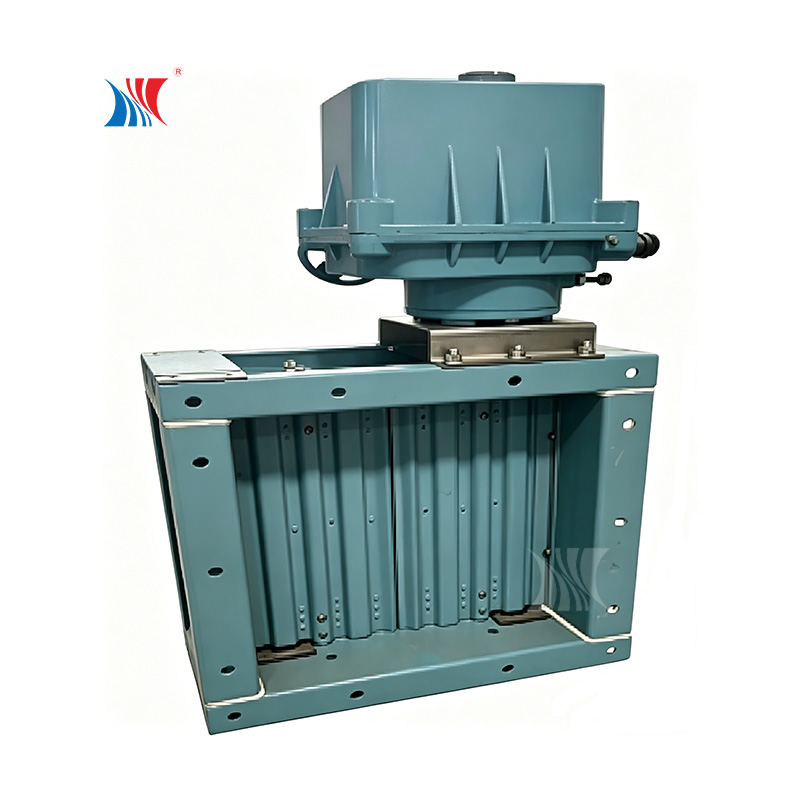
Why Check Valve Placement Is Critical in Large-Diameter Ventilation Systems
Preventing Backdraft and Cross-Contamination in High-Volume Airflows
In large ventilation systems handling high-volume airflows, the momentum of moving air can overwhelm weak seals—causing reverse flows that lead to backdraft or cross-contamination. Proper check valve placement is the primary defense. When positioned immediately downstream of potential contamination sources—such as fume hood exhausts or isolation rooms—a check valve creates a physical barrier that closes rapidly upon flow reversal. Its dynamic response must match the system’s flow profile; slower-acting designs risk allowing a brief slug of contaminated air to pass before fully seating. In hospital HVAC systems, where airborne pathogen containment is non-negotiable, even a millisecond delay due to poor placement can permit infectious particles to migrate into clean zones.
Strategic placement also leverages gravity-assisted closure in vertical risers, ensuring reliable sealing during power failures or fan shutdowns. Grouping multiple exhaust streams behind individual check valves prevents pressure interactions that could force fumes from one duct into another. Without these barriers, high air momentum can turn branch connections into unintended intakes—compromising indoor air quality across entire zones. To verify real-world performance, commissioning tests must simulate worst-case back-pressure scenarios and confirm each valve closes within the permitted leakage limit per ASHRAE 62.1–2022 Appendix C.
Pressure Differential Loss Dynamics in Ducts Over 600 mm
The pressure penalty of a check valve becomes pronounced as duct diameter increases. For ducts exceeding 600 mm, the valve’s resistance coefficient—often 2.5 for a standard swing check—translates into substantial static pressure drops. Consider a 1,000 mm duct conveying 10 m/s of air: dynamic pressure is roughly 60 Pa; with K = 2.5, the check valve alone dissipates 150 Pa (0.6 in. w.g.). This loss directly reduces system efficiency and increases fan energy demand. Pressure loss cumulates across each check valve in series, making it essential to minimize their number through strategic placement—not redundancy.
Downstream wake turbulence further amplifies friction losses in the following straight duct run. Designers must weigh these dynamics against the critical role of backflow prevention: locating the valve where pressure differentials are smallest—such as near the fan discharge, where static regain is highest—can significantly mitigate impact. In retrofit projects, replacing undersized swing checks with low-loss alternatives like silent or dual-plate designs has recovered up to 30% of the pressure drop in field measurements (2022). Optimizing placement thus requires a holistic analysis of the duct network’s pressure budget—not just component selection.
Correct Check Valve Orientation and Mounting for Reliable Operation
In large-diameter ventilation systems, orientation directly determines how reliably a check valve seals and how quickly it responds to shifts in airflow. Every valve body carries a flow-direction arrow; ignoring it—even with a well-sized unit—can cause jamming or failure to close. Beyond that basic rule, the choice between horizontal and vertical installation governs sealing integrity, closure speed, and long-term wear.
Horizontal vs. Vertical Installation: Effects on Sealing Integrity and Response Time
Horizontal installation suits swing-type check valves, where the disc hangs from a top-hinged pin. With the hinge perfectly level, the disc swings freely, and on flow cessation, gravity pulls it back against the seat. In steady, high-volume systems, this yields tight sealing because disc weight acts perpendicular to the sealing face. However, fluctuating or pulsating flows can induce disc bounce—accelerating seat wear and reducing long-term integrity.
Lifting-disc or spring-loaded check valves require vertical mounting with upward flow. When installed horizontally, lift-type discs lose gravity assistance and may hang partially open or close sluggishly—raising backflow risk without strong spring compensation. While spring-loaded designs improve responsiveness, spring force must still overcome static friction, delaying closure by milliseconds that matter in high-velocity ducts. Lab testing compliant with ASME standards (2022) shows vertically mounted, spring-assisted lift valves achieve full closure within 0.2 s after flow stops—whereas horizontally mounted swing discs of the same nominal size may take twice as long, especially if hinge alignment is imperfect. That delay can permit momentary backdraft sufficient to contaminate upstream zones.
Gravity-Assisted Closure Thresholds for Ducts ≥800 mm
In ducts 800 mm or larger, disc or flap mass becomes substantial—and gravity alone often cannot guarantee fast, positive closure against air column momentum. Swing check valves in these sizes typically require a minimum back-pressure threshold of 50–150 Pa to initiate closure once flow ceases. Below this, the disc may hover slightly open, enabling high-volume reverse leakage. For such applications, engineers increasingly specify counter-weighted or spring-loaded opposed-blade dampers, whose closure force can be tuned independently of gravity.
In vertical up-flow configurations, lift-type valves benefit from consistent gravity-assisted closure—making them more predictable than swing types at scale. Design codes recommend that for any duct ≥800 mm, the valve’s closure mechanism deliver at least 1.5× the static disc weight in closing force. This ensures rapid, positive seating—even during abrupt system pressure drops—preventing reverse flow when it matters most.
Sizing, Structural Support, and Integration of Check Valves in Industrial Ductwork
Flange Reinforcement and Load Distribution for Check Valves >1,000 mm
Check valve installations exceeding 1,000 mm in diameter demand robust flange reinforcement to manage substantial static and dynamic loads. The valve body and mating flanges must resist bending moments induced by duct misalignment, thermal expansion, and the weight of the assembly itself. Without proper support, excessive flange stress leads to gasket leakage and impaired sealing integrity.
A bolted connection designed to ASME B16.47 Series A or B standards distributes clamping force evenly—but oversized ducts often require additional gusset plates or welded stiffening rings on adjacent ductwork. In vertical orientations, gravity loads concentrate on the lower flange, so a dedicated support saddle or structural steel frame beneath the valve prevents sag. Load distribution should be verified via finite element analysis to identify high-stress areas before fabrication. During commissioning, torque checks on all flange bolts—tightened in a star pattern to 70% of yield strength—confirm uniform compression and ensure reliable operation under fluctuating system pressures.
Commissioning and Performance Validation of Installed Check Valves
Static and Dynamic Pressure Testing per ASHRAE 62.1–2022 Appendix C
System commissioning transforms a check valve from a static component into a verified safety device. The process begins with static pressure testing to confirm airtight closure and structural soundness under no-flow conditions. Technicians seal the downstream side and apply a specified positive pressure; a measurable pressure drop over time—as defined in the commissioning plan—indicates leaking valve seats or compromised body seals. This test validates the valve’s foundational function: preventing reverse flow when the system is idle.
Dynamic pressure testing then evaluates performance under operational airflow, per ASHRAE 62.1–2022 Appendix C. A calibrated flow grid measures the pressure differential across the valve while fully open. Comparing this reading to the manufacturer’s published pressure-drop curve reveals whether the valve imposes excessive energy waste on the fan system. Simultaneously, a high-precision micro-manometer records static pressure fluctuations to detect flutter caused by turbulent flow. A successful dynamic test confirms the check valve achieves stable, full-open positioning—with pressure losses within design tolerance—ensuring both system efficiency and functional reliability.
FAQ
Why is check valve placement important in ventilation systems?
Proper placement ensures that backflow and cross-contamination are prevented, protecting air quality and maintaining system efficiency.
What are the benefits of gravity-assisted closure in ventilation systems?
Gravity-assisted closures ensure reliable sealing during power failures or fan shutdowns, especially in vertical risers.
How does duct size affect check valve performance?
Larger ducts increase the pressure penalty of the valve, so it's essential to consider the valve’s resistance coefficient to optimize system efficiency.
What challenges arise with check valve orientation?
Improper orientation can lead to jamming, delayed closure, and compromised sealing integrity in systems with fluctuating or high-velocity airflows.
How can valve sealing integrity be validated during commissioning?
By conducting static and dynamic pressure tests, technicians can ensure that the check valve closes airtight and operates efficiently under real-world conditions.
Table of Contents
- Why Check Valve Placement Is Critical in Large-Diameter Ventilation Systems
- Correct Check Valve Orientation and Mounting for Reliable Operation
- Sizing, Structural Support, and Integration of Check Valves in Industrial Ductwork
- Commissioning and Performance Validation of Installed Check Valves
-
FAQ
- Why is check valve placement important in ventilation systems?
- What are the benefits of gravity-assisted closure in ventilation systems?
- How does duct size affect check valve performance?
- What challenges arise with check valve orientation?
- How can valve sealing integrity be validated during commissioning?